Free shipping on all orders over $150! Use coupon code FREESHIP at check out
Vortex Tubes
C.C. Steven, your ANSWER to compressed air challenges.
PROCESS AND SPOT COOLING WITH VORTEX TUBES
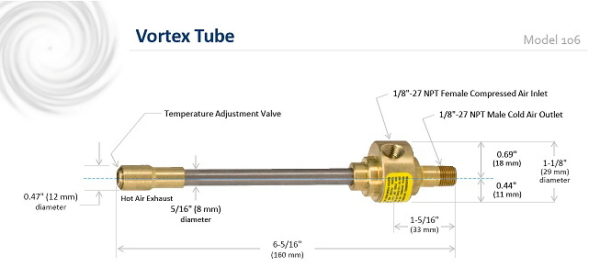
Vortex tubes are a compact source of refrigeration and cooling, with models ranging from 6 – 13 inches (150 – 330 mm) long and cooling capacities ranging from 100 – 6000 BTU/hour (29 – 1757 watts). Vortex tube performance is easily adjustable by changing the inlet air pressure, ratio of cool air to exhaust or by changing the generator in the tube itself. And while normally used for cooling, vortex tubes can also be used for heating applications, merely by channeling the exhaust hot air to the application.
Vortex tube technology was invented by French physicist Georges Ranque in 1930, and first developed for industrial use by Vortec in the 1960s. Since then, vortex tubes have been applied for a wide range of cooling applications on machines, assembly lines, in processes and for testing and measurements.
Benefits
- Cools instantaneously
- Lowest cost per unit of refrigeration of any cooling technique
- Fully adjustable cooling, easily moved from site to site as needed
- Fits to provide cooling in the most confined areas
- Lowest maintenance requirements of any refrigeration technique
- Environmentally friendly, with no refrigerants or chemicals needed
- Easy to install, just connect compressed air and go
Features
- Maintenance free, with no moving parts
- Cycle repeatability within +/- 1 deg
- Drops compressed air inlet temperature by up to 100 deg F (55 deg C)
- No electricity required at the cooling site
- Cools without refrigerants, as low as -40 deg
- Compact and lightweight, highly transportable
- Adjustable for varying cooling needs
- Available heating capacity using the same tube, up to 200 deg F (93 deg C)
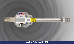
- Available in both aluminum (208 and 308) and stainless steel (208SS) models
- Replacement generators available for modification of cooling or upon contamination
Specifications
| Model# | 106-2-H | 106-4-H | 106-8-H | 208-11-H |
| Material of Construction | Brass/Stainless Steel | Brass/Stainless Steel | Brass/Stainless Steel | Aluminum |
| Inlet, inch, NPT | 1/8 | 1/8 | 1/8 | 1/4 |
| Cooling Capacity (BTU/hr) | 100 | 200 | 400 | 640 |
| Air Consumption @ 100 psig (scfm) | 2 | 4 | 8 | 11 |
| Inlet, Female or Male | F | F | F | F |
| Model# | 208-15-H | 208-25-H | 208-11-HSS | 208-15-HSS |
| Material of Construction | Aluminum | Aluminum | Stainless Steel | Stainless Steel |
| Inlet, inch, NPT | 1/4 | 1/4 | 1/4 | 1/4 |
| Cooling Capacity (BTU/hr) | 900 | 1500 | 640 | 900 |
| Air Consumption @ 100 psig (scfm) | 15 | 25 | 11 | 15 |
| Inlet, Female or Male | F | F | M | M |
| Model# | 208-25-HSS | 308-35-H | 328-50-H | 328-75-H | 328-100-H |
| Material of Construction | Stainless Steel | Aluminum | Aluminum | Aluminum | Aluminum |
| Inlet, inch, NPT | 1/4 | 1/4 | 1/2 | 1/2 | 1/2 |
| Cooling Capacity (BTU/hr) | 1500 | 2650 | 3000 | 4500 | 6000 |
| Air Consumption @ 100 psig (scfm) | 25 | 35 | 50 | 75 | 100 |
| Inlet, Female or Male | M | F | M | M | M |
Vortex Tubes
Air that rotates around an axis (like a tornado) is called a vortex. A vortex tube creates cold air and hot air by forcing compressed air through a generation chamber, which spins the air at a high rate of speed (1,000,000 rpm) into a vortex. The high speed air heats up as it spins along the inner walls of the tube toward the control valve. A percentage of the hot, high speed air is permitted to exit at the valve. The remainder of the (now slower) air stream is forced to counterflow up through the center of the high speed air stream in a second vortex. The slower moving air gives up energy in the form of heat and becomes cooled as it spins up the tube. The inside counterflow vortex exits the opposite end as extremely cold air. Vortex tubes generate temperatures as much as 100 deg F (56 deg C) below the inlet air temperature. The fraction of hot air exhausted can be varied to change the outlet cold air temperature, with more exhaust resulting in a colder cold air stream (with lower flow rate), and less exhaust resulting in a warmer cold air stream (and higher flow rate).
Vortex Tubes
Vortex Tubes are an effective, low cost solution to a wide variety of industrial spot and process cooling needs.
With no moving parts, a vortex tube spins compressed air to separate the air into cold and hot air streams. While French physicist Georges Ranque is credited with inventing the vortex tube in 1930, ITW Vortec was the first company to develop and apply this phenomenon into practical and effective cooling solutions for industrial use.

How a Vortex Tube Works
Fluid (air) that rotates around an axis (like a tornado) is called a vortex. A Vortex Tube creates cold air and hot air by forcing compressed air through a generation chamber which spins the air centrifugally along the inner walls of the Tube at a high rate of speed (1,000,000 RPM) toward the control valve. A percentage of the hot, high-speed air is permitted to exit at the control valve. The remainder of the (now slower) air stream is forced to counterflow up through the center of the high-speed air stream, giving up heat, through the center of the generation chamber finally exiting through the opposite end as extremely cold air. Vortex tubes generate temperatures down to 100°F below inlet air temperature. A control valve located in the hot exhaust end can be used to adjust the temperature drop and rise for all Vortex Tubes.
Applications:
Vortex Tubes have a very wide range of application for industrial spot cooling on machines, assembly lines and processes.
- Cool machining operations
- Set solders and adhesives
- Cool plastic injection molds
- Dry ink on labels and bottles
- Dehumidify gas samples
- Cool heat seal operations
- Thermal test sensors and choke units
- Cool cutter blades
- Temperature cycle parts
Sub-Zero Spot Cooling from Compressed Air
Features & Benefits
- Uses only compressed air – no electricity or refrigerants
- Maintenance free – no moving parts
- Exceptionally reliable
- Compact and lightweight
- Cycle repeatability within ± 1°
- Drops inlet temperature by up to 100°F
| Vortex Tube Models and Performance Specifications: | ||||||
Compressed Air Pressure, 100psig |
Compressed Air Pressure, 6.9 BAR |
|||||
| Model |
SCFM
|
Temp. Drop *F |
BTUH |
SLPM Consumption |
Temp. Drop *C |
KCAL/H |
| 106-2-H | 2 | 61 | 100 | 57 | 34 | 25 |
| 106-4-H | 4 | 80 | 255 | 113 | 44 | 64 |
| 106-8-H | 8 | 81 | 400 | 227 | 45 | 101 |
| 208-11-H | 11 | 84 | 640 | 312 | 47 | 161 |
| 208-15-H | 15 | 84 | 900 | 425 | 47 | 227 |
| 208-25-H | 25 | 67 | 1500 | 708 | 37 | 378 |
| 308-35-H | 35 | 76 | 2650 | 992 | 42 | 668 |
| 328-50-H | 50 | 79 | 3000 | 1416 | 44 | 756 |
| 328-75-H | 75 | 85 | 4500 | 2125 | 47 | 1134 |
| 328-100-H | 100 | 78 | 6000 | 2833 | 43 | 1512 |
BTUH (kcal/H) capacity based upon 70*F (21*C) compressed air dried to a dewpoint of -40*F (-40*C).
DESCRIPTION
Vortex tubes solve thousands of industrial cooling problems using only factory compressed air as a power source. A Vortex Tube converts ordinary compressed air into two air streams — one hot and one cold. With no moving parts, no electricity, and no refrigerants, a Vortex Tube can produce refrigeration up to 6000 BTUH or temperatures to -50F using only factory compressed air at 100PSI. A control valve in the hot air exhaust adjusts temperatures, flows, and refrigeration over a wide range.
VORTEX TUBE PHENOMENON
First discovered quite by accident by Georges Ranque, a French physicist in 1930, the effects of a Vortex Tube are still an unexplained phenomenon to many. Vortec Corporation was the first company to develop technology for converting the Vortex Tube phenomenon into practical, effective cooling solutions for industrial applications. For over 40 years, Vortec Corporation has been developing patents and technology to expand and refine Vortex Tube applications.
The drawing above illustrates how a Vortex Tube works. Compressed air enters a tangentially drilled stationary generator which forces the air to spin down the long tube’s inner walls toward the hot air control valve, achieving sonic speeds of up to 1,000,000 RPM.
A percentage of this air, now at atmospheric pressure, exits through the needle valve at the hot air exhaust. The remaining air is forced back through the center of the sonic-velocity airstream where, still spinning, it moves at a slower speed, causing a simple heat exchange to take place. The inner, slower-moving air column gives up heat to the outer, faster moving air column. When the slower inner air column exits through the center of the stationary generator and out the cold exhaust, it has reached an extremely low temperature.
SPECIFICATIONS
The volume and temperature of cold air produced by a Vortex Tube are controlled by the valve in the hot air exhaust. This volume (Cold Fraction) is the percent of total input air released through the cold exhaust. For example, if the total volume of compressed air input is 15SCFM and the Cold Fraction is 70%, then 10.5 SCFM exits the cold end and 4.5 SCFM exits the hot end. A high Cold Fraction. (i.e., more than 50% or the input air exiting the cold air exhaust), produces the maximum efficiency — the greatest BTUH output. This occurs at Cold Fractions of 60% to 70%, where the amount of air released at the cold exhaust and the temperature drop are optimized. Cooling machining operations, electronic controls, liquid baths, and workers will require high Cold Fractions for maximum refrigeration.
A low Cold Fraction, (i.e., less than 50% of the input air exiting through the cold air exhaust), produces the lowest temperatures, but with reduced airflow. Colder temperatures are useful for cooling glass. laboratory experiments, and testing of electronic components.
AIRFLOW
The total discharge (hot and cold) in SCFM from a Vortex Tube is proportional to absolute inlet pressure. To approximate the total flow for a given inlet pressure, use the following simplified formula:
[(inlet PSIG +15) x CFM rating of generator]/115 = total flow
VORTEX TUBE PERFORMANCE
The Vortex Tube Performance chart shown below illustrates the effects different Cold Fraction settings will have on the drop and rise in Vortex Tube temperatures. Both the inlet pressure and the Cold Fraction setting are important factors in Vortex Tube cooling performance.
The chart below assumes an inlet air temperature of 70F. Higher inlet temperatures, excessive moisture in the air supply, or excessive back pressure at either the hot or cold air exhaust will reduce the cooling performance of a Vortex Tube. A clean Vortex Tube operating with a constant inlet pressure and temperature will deliver temperatures maintained within + or – 1 degree F.
| Inlet Pressure PSIG | Cold Fraction % | ||||||
| 20 | 30 | 40 | 50 | 60 | 70 | 80 | |
| 20 | 61.5 | 59.5 | 55.5 | 50.5 | 43.5 | 36.0 | 27.5 |
| 14.5 | 24.5 | 36.0 | 49.5 | 64.0 | 82.5 | 107 | |
| 40 | 88.0 | 85.0 | 80.0 | 73.0 | 62.5 | 51.5 | 38.0 |
| 20.5 | 35.0 | 51.5 | 71.0 | 91.5 | 117.0 | 147 | |
| 60 | 104 | 100 | 93.0 | 84.0 | 73.0 | 59.5 | 44.5 |
| 23.5 | 40.0 | 58.5 | 80.0 | 104 | 132 | 168 | |
| 80 | 115 | 110 | 102 | 92.0 | 80.0 | 65.5 | 49.0 |
| 25.0 | 43.0 | 63.0 | 86.0 | 113 | 143 | 181 | |
| 100 | 123 | 118 | 110 | 99.0 | 86.0 | 70.5 | 53.0 |
| 26.0 | 45.0 | 66.5 | 91.0 | 119 | 151 | 192 | |
| 120 | 129 | 124 | 116 | 104 | 90.5 | 74.0 | 55.0 |
| 26.0 | 46.0 | 69.0 | 94.0 | 123 | 156 | 195 | |
| 140 | 135 | 129 | 121 | 109 | 94.0 | 76.0 | 56.5 |
| 25.5 | 46.0 | 70.5 | 96.0 | 124 | 156 | 193 | |
| Figures shaded in grey give temperature drop of cold air, degrees F | |||||||
| Figures on the second line give temperature rise of hot air, degrees F | |||||||
MODELS OFFER FLEXIBILITY
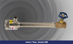
Vortec Corporation has developed four standard Vortex Tube sizes — Model 106, Model 208, Model 308, and Model 328. Each model can be sized to provide different CFM ratings and cooling capacities by selecting the appropriate generator
Vortec’s four standard Vortex Tube models, each offering a variety of generators, provide the full range of cooling capacity that is economically practical for cooling with Vortex Tubes. This type of flexibility guarantees each Vortex Tube can be efficiently sized for the cooling needs of the application.
Sign Up For Our Newsletter

A name you can trust. Doing business since 1978!


